自己打造一台恩尼格玛密码机
在对称加密学当中,恩尼格玛机绝对是承前启后的存在。它将密码学研究从以前的语言文字学中心完全转移到了数学身上。在这里牵涉的密码并不是我们平时邮箱、银行帐号那种狭义概念,那种顶多叫做口令。这里说的密码就是通过某种映射方式,把一篇文章变得面目全非,以达到保密效果;只有特定的转换规律才能将其解密。这篇文章适于电脑控、军事控、历史控、数学控阅读,请做好烧脑准备。
EDIT: This Instructable has won Second prize in the 2013 Radio Shack Microcontroller Contest. Thank You to all who voted!
按:这个作品是 2013 年无线电单片机竞赛的亚军。感谢所有支持这个作品的你们!
EDIT2: An Open Enigma with fake Standup Nixie Tubes like the ones pictured in this Instructable will soon be available as a Special Kickstarter edition.
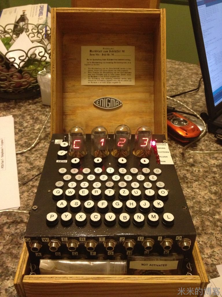
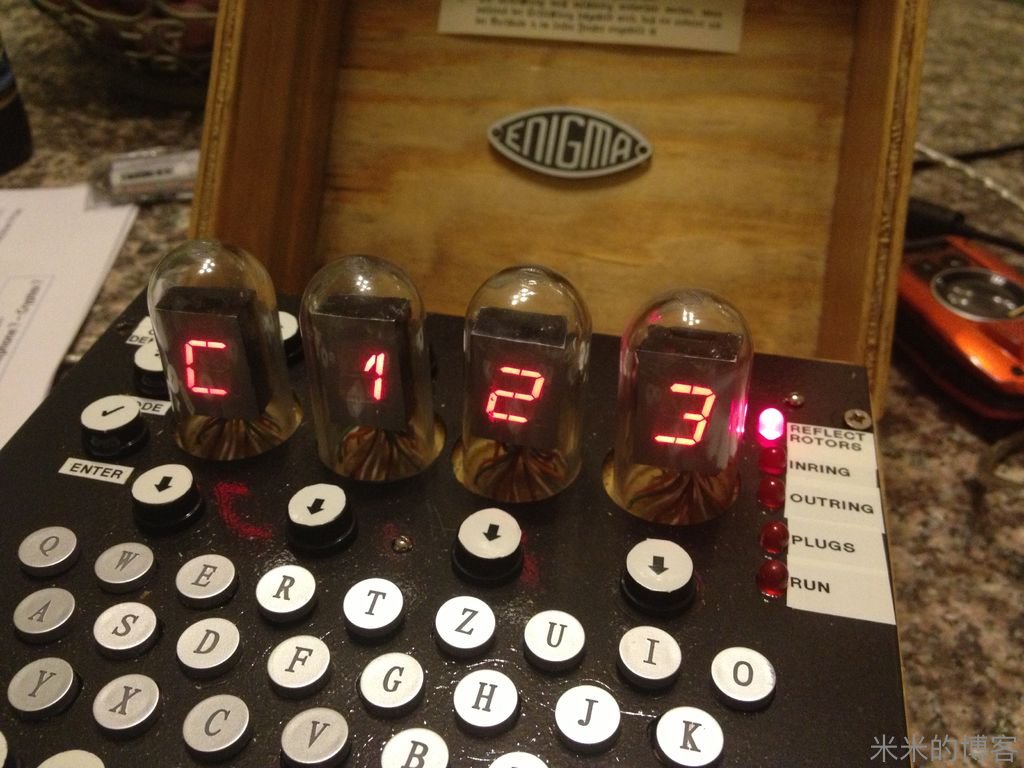
This is our very first Instructable and this step by step guide will show you how to build a fully functional electronic replica of the world famous German Enigma machine. This Arduino based Open Source project is able to encrypt & decrypt any Enigma M4 encoded message.
这是我们的初号机。以下教程将手把手教你如何完美复刻史上著名的德国恩尼格玛密码机。这个基于 Arduino 的开源程序能够加解密任何 Enigma 机 M4 型(海军型)的信息。
This first ever fully functional Open Source Enigma "exact" Replica was inspired by the Kid's Game to Arduino Enigma Machine by sketchsk3tch.
这个第一台全功能开源完美 Enigma 机复制品是根据 sketchsk3tch 写的《Kid's Game to Arduino Enigma Machine(从儿童玩具到 Arduino 恩尼格玛机)》所作。
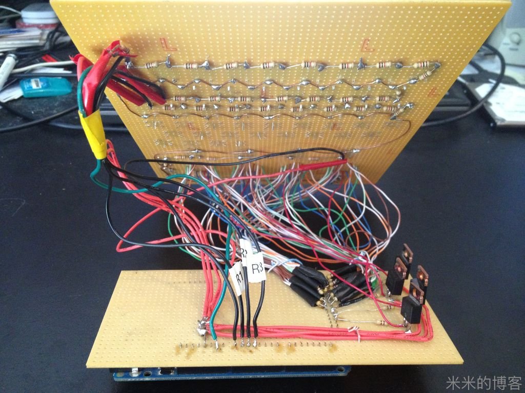
Using Multiplexing for the LEDs, this circuit with 115 light emitting diodes uses only 38 pins and the 36 push buttons use only 4 pins total thanks to properly placed resistors (and the P-Channel MOSFETs) in the keyboard loop. These 4 16-Segment displays & an LED for each keyboard button would add up quickly the total number of pins required and even the Arduino Mega would have ran out of pins without the 2 methods mentioned above....
采用多路复用 LED 电路,仅用 38 个针脚的 115 个发光二极管和 4 个针脚的 36 个按键所连接的整个电路,全靠在键盘回路里准确放置的电阻以及 P 沟道场效应晶体管得以实现。要不然,4 个 16 段显示器,以及每个按键上的 LED 将大幅增加所需针脚总量 —— 即使用了 Arduino Mega 板,但如果没用上述两个方法,电路也不能如此简洁。
In response to the overwhelming demand, we designed the PCB and made it available through www.stgeotronics.com. Skip to Step 10 & beyond for more info. We also offer it as a complete electronics kit & an assembled & tested complete product.
面对电路的超额需求,我们在 http://www.stgeotronics.com 设计了专用的 PCB 板。直接跳到第 10 步和以后的步骤可以找到更多信息。同时,我们也发布了测试过的完整电子组装套装。
Step 1: Proof of Concept on Breadboard
第一步:面包板上的论证
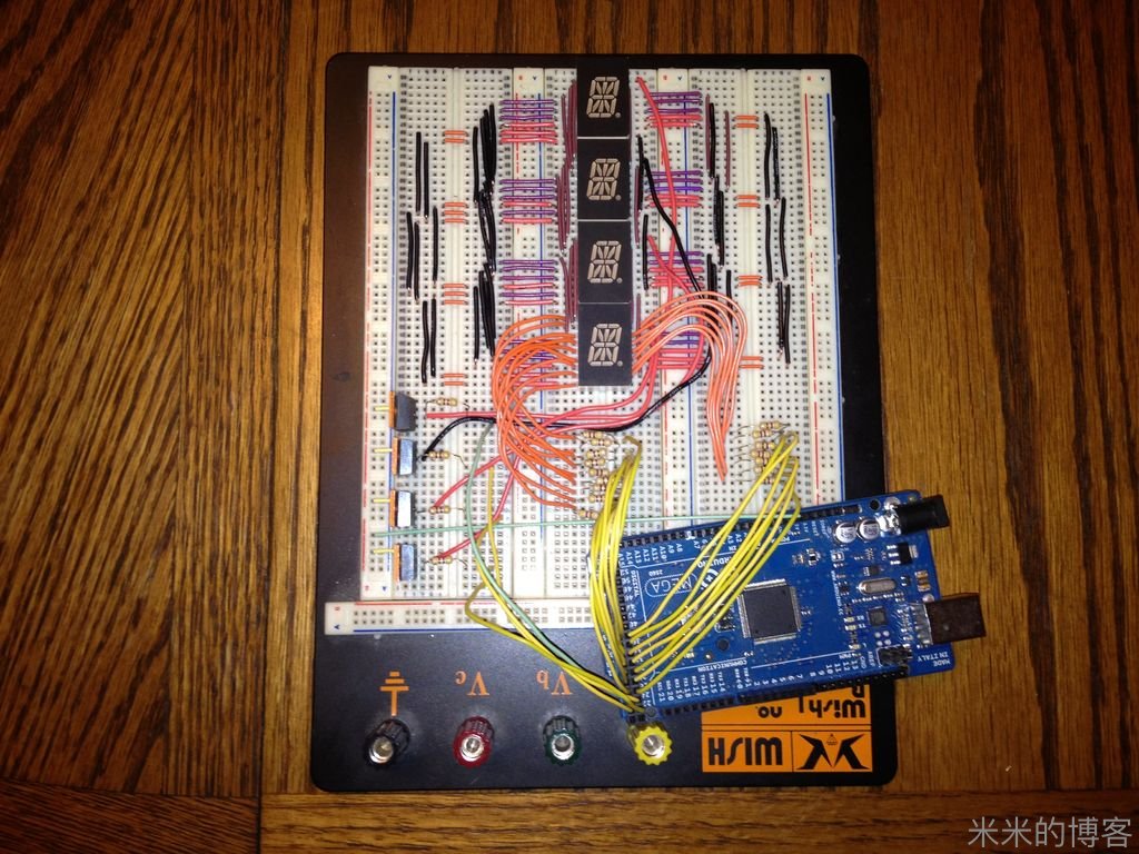
Before going all out on the development of this electronic Enigma replica, we wanted to make sure we could properly drive the 16 Segment LEDs. If we can do that, than we will be able to do everything as the rest is only Math...
在开始制作电子 Enigma 机之前,我们先要确保能驱动 16 段 LED 显示。如果成功,我们就能做接下来的所有步骤 —— 除了数学上的问题,一切都是浮云。
Step 2: Gather the Raw Materials...
第二步:万事具备
You will need:
你所需要的是:
1 Arduino Mega
1 个 Arduino Mega 2560 板26 Alpha Buttons
26 个字母按键26 1/4" Jacks Mono
26 个 1 / 4 英寸单通道母接口10 1/4" Plugs Mono
10 个 1 / 4 英寸单通道公接口36 Pushbuttons
36 个机械按钮1 On/Off/On Switch
1 个单刀三掷开关4 16Segment Orange
4 个 16 段橙色 LED 显示4 Injection molded 2-Liter Soda Bottle preform (test tubes)
4 个注塑 2 升汽水瓶罩子1 Case Plywood
1 个胶合板盒子1 Hinge & Hooks
一个铰链1 Half-Mortise Lock
一个半榫接锁1 Perfboard
一个接线盘38 Resistors 470 Ohms
38 个 470 欧电阻40 Resistors 1K Ohms
40 个 1 千欧电阻7 IRF9Z24N P-Channel MOSFET
7 个 IRF9Z24N P 沟道场效应晶体管1 Piece of Metal & Spray paint
1 块金属片以及喷漆
Optional:
可选项:
Battery Case
电池盒Rechargeable Batteries
充电电池Battery Charger/Connectors
充电电池
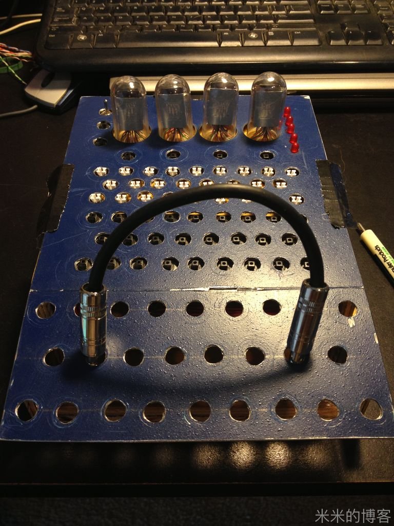
If we were to do it again, we wouldn't use 1/4" Jacks & Plugs as these are pretty big and tend to overwhelm the whole Enigma. Banana plugs & jacks are smaller & closer to the original connectors used by the real German Enigmas.
我们真要做的时候,是不会用 1 / 4 英寸接口的。它们太大的体积几乎要超过整个恩尼格玛机。香蕉插头体积较小,而且比原版德国 Enigma 机结合得更紧密些。
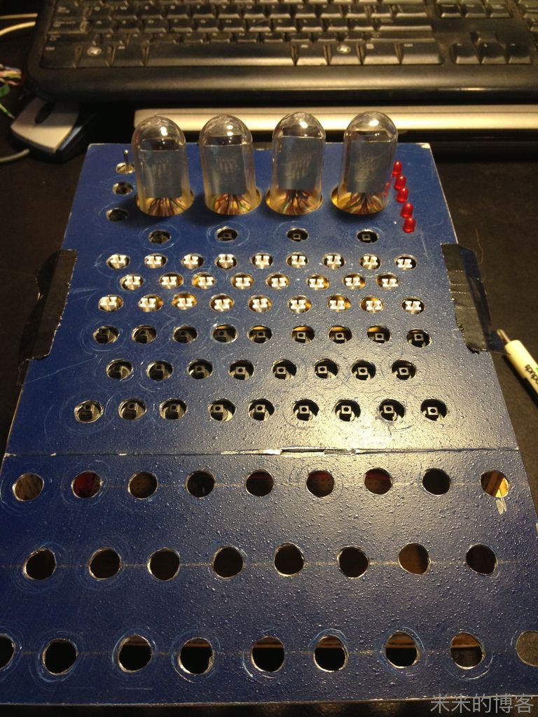
Step 3: Lay the Components Down
第三步:布置零件
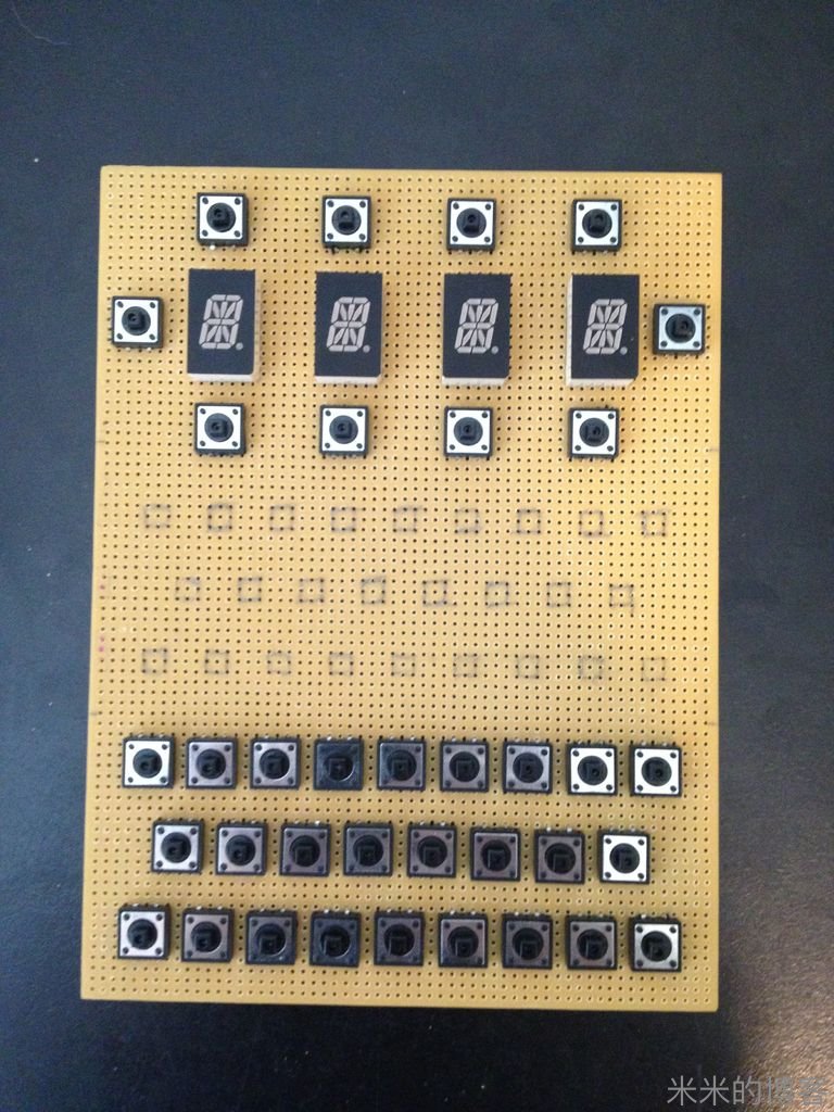
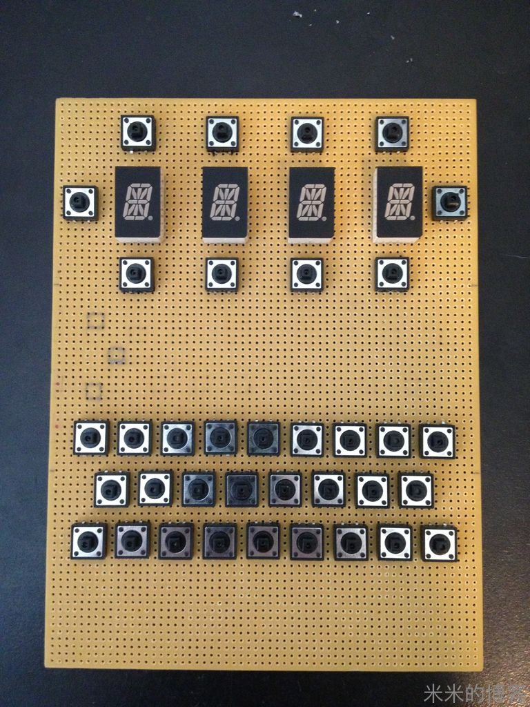
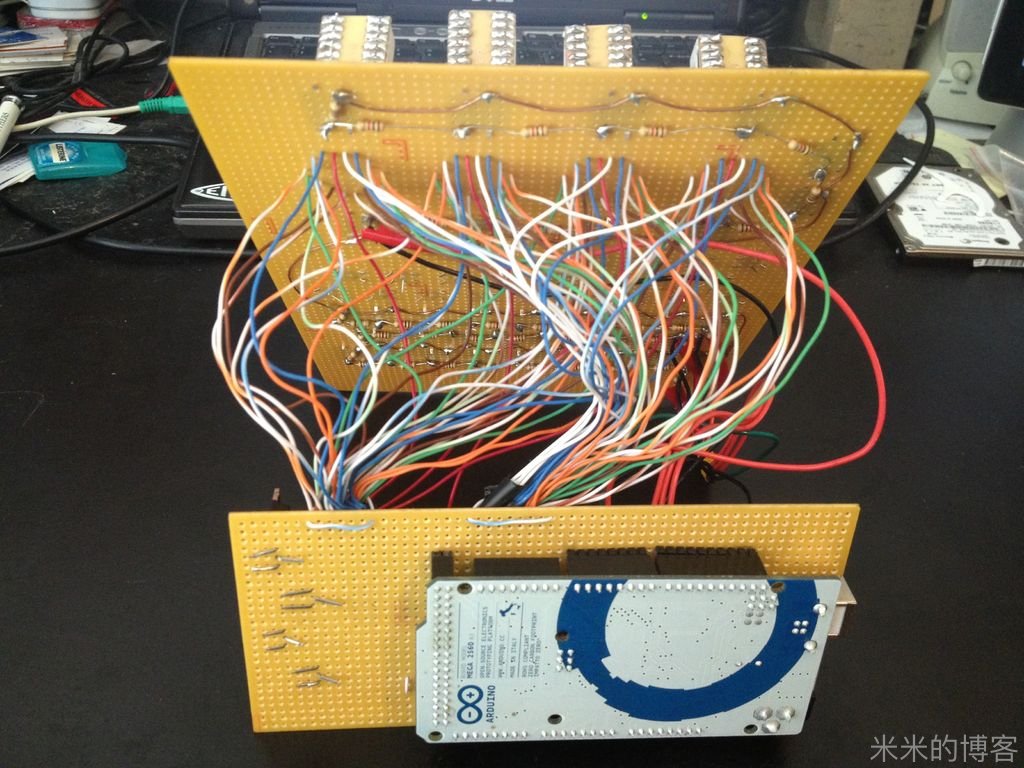
The Radio Shack 6" x 8" Micro Perboard is the perfect size to host all components as it provides just the right amount of space to fit everything on & will fit perfectly inside the Enigma box.
6 * 8 寸无线电面包版是最适合放置所有元件的,既不多余也不拥挤,而且和 Enigma 机盒子内部完美吻合。
We started dividing the space on the Perfboard equally between the 3 regions, but realized soon that this would make the electronic Enigma longer than the real one, so we compressed everything down to the proper spacing.
最初我们将面包板等分为三块区域,但很快意识到,如此一来,电子版 Enigma 机将比原版的机械 Enigma 机长。于是我们将所有零件缩放到正好够占用的空间。
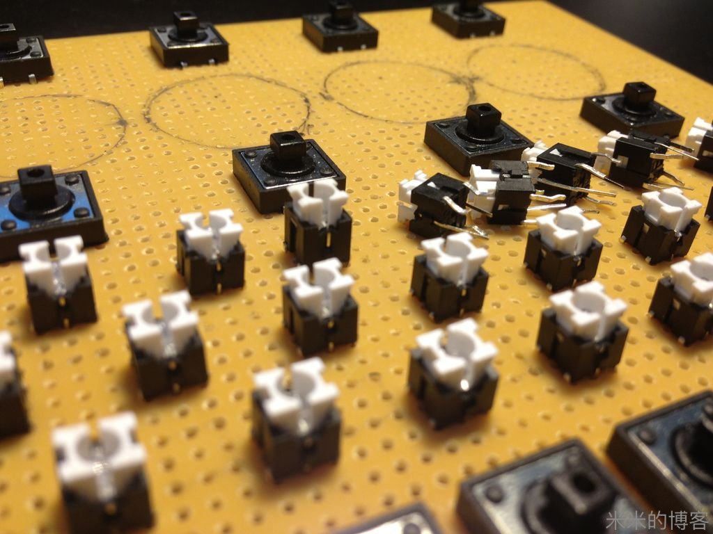
Once satisfied with the positioning of each components, next step is soldering.
每个元件位置就绪,下一步就是焊接。
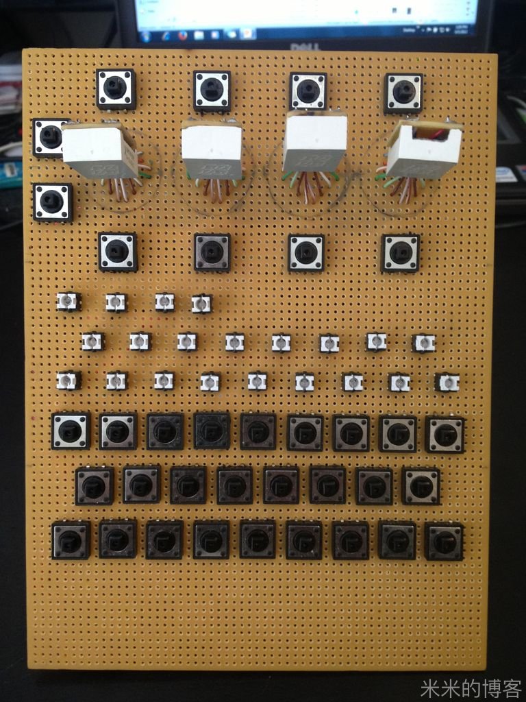
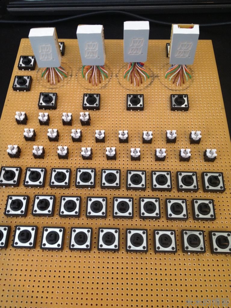
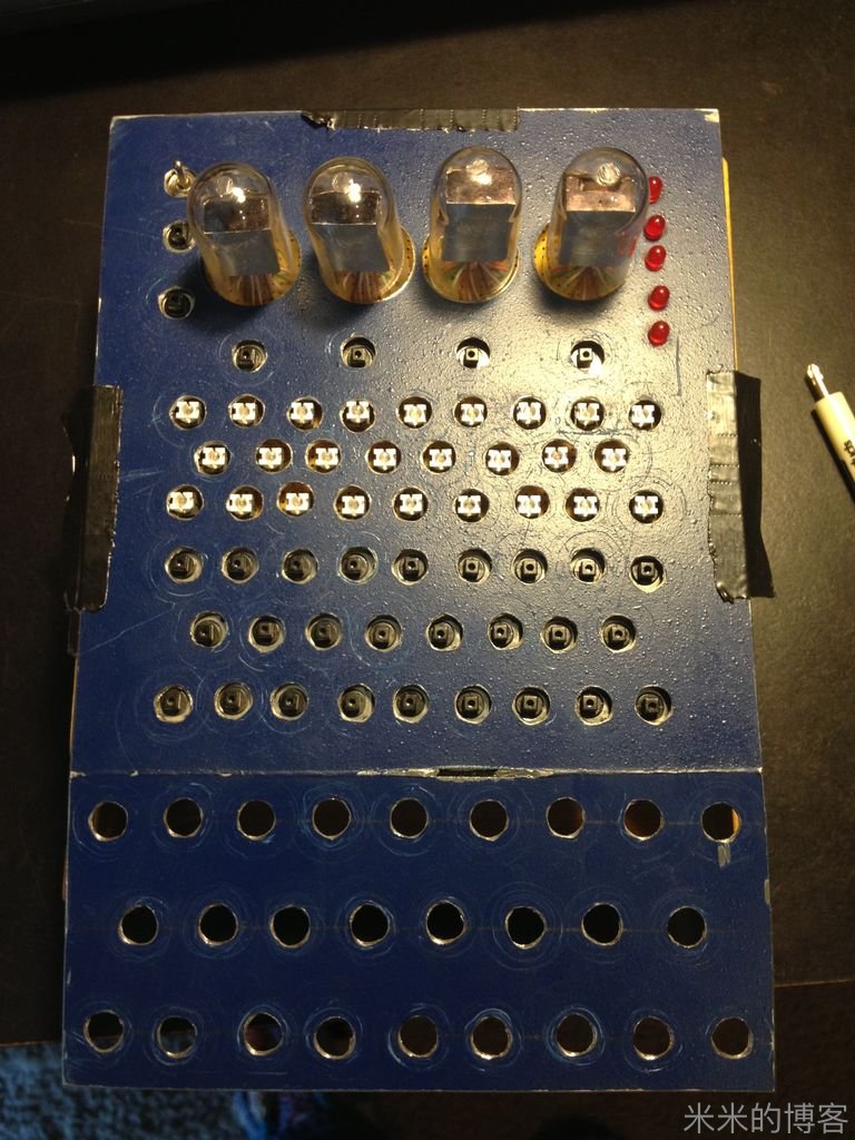
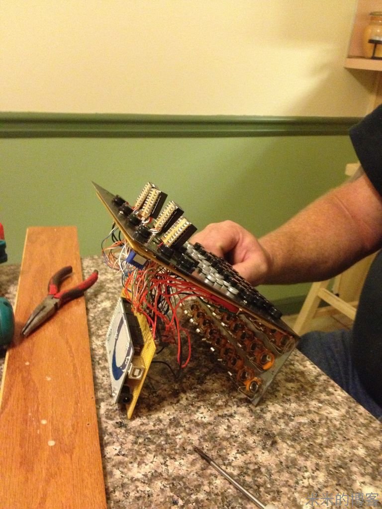
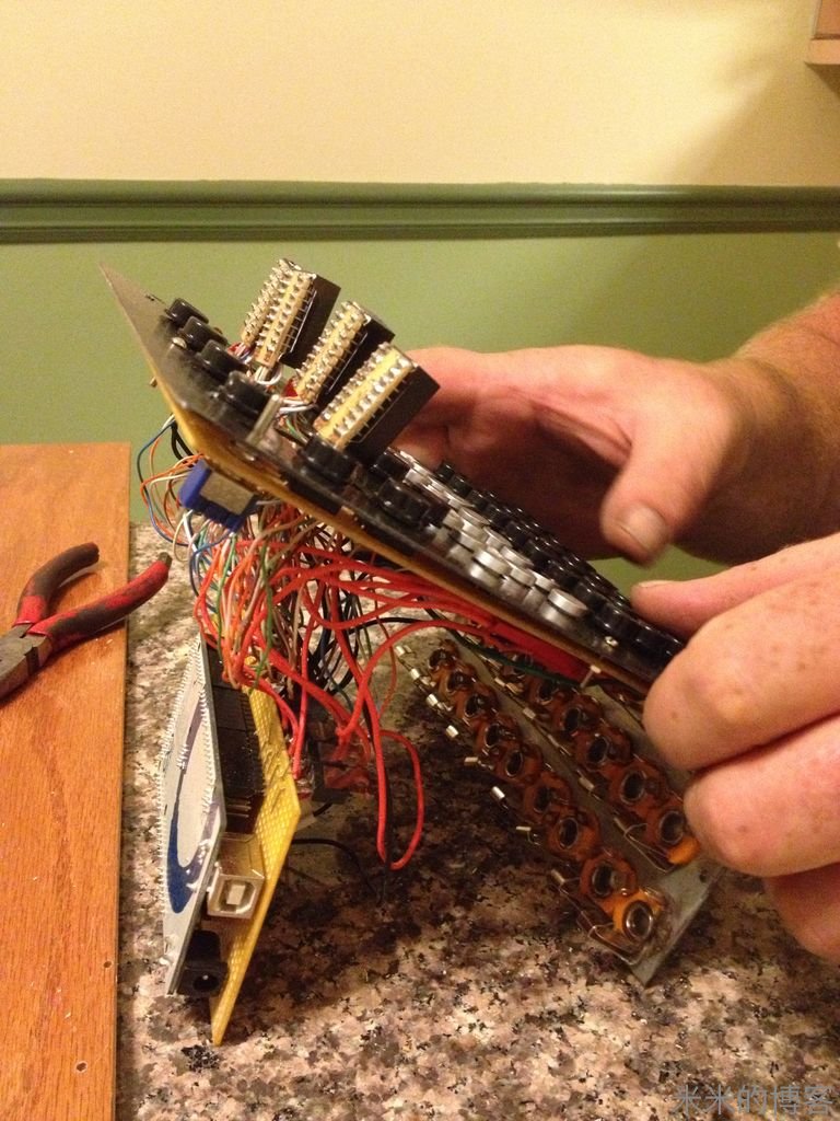
Step 4: Soldering, Soldering & a Little More Soldering
第四步:我焊,我焊,我焊焊焊……
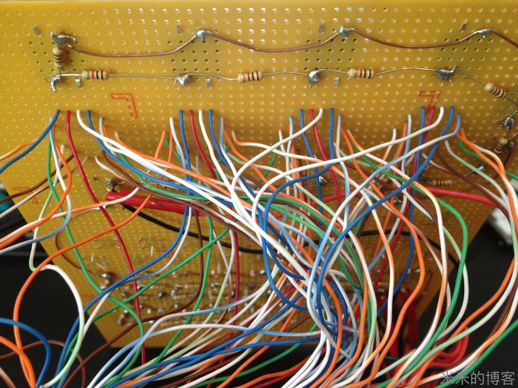
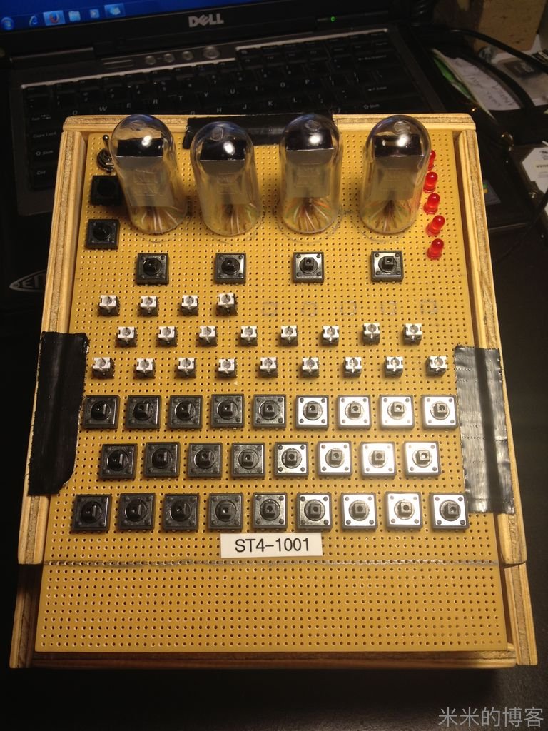
OK, this proved to be the most solder I have used on a single project ever. With 18 pins per 16 Segment, times 4 plus 26 keyboard keys + 26 keyboard lamps + a few LEDs & 1 SPDT on/off/on switch, that was a lot of solder.
好吧,在单一作品身上,我从没焊接如此多次。16 段显示的 18 个针脚,还有 26 个字母键乘以每个 4 个脚,外加 26 个键盘灯,一些其他 LED,一个三掷开关,真乃「成吉思焊」。
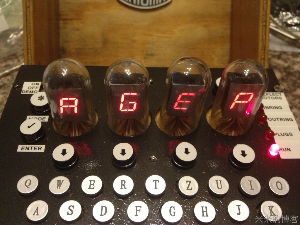
Our decision to raise the 16 Segment displays up to make them look like old-time Nixie tubes certainly added a lot of solder points!
当初我们的决定是使这些 16 段 LED 显示看起来像老式电子管的感觉,增加了不少焊点,「巨焊」!
Our Arduino Mega Pin assignment:
Arduino Mega 板上针脚的分配:
17 Segments:
Seg Pin Wire DuinoPin
a 2 blue 24
b 1 white 22
c 16 wh-bl 25
d 13 green 31
e 9 wh-br 38
f 8 brown 36
g 6 green 32
h 5 wh-or 30
k 4 orang 28
m 3 wh-bl 26
n 17 blue 23
p 15 orang 27
r 12 wh-gr 33
s 11 brown 35
t 7 wh-gr 34
u 14 wh-or 29
dp 10 wh-br 37
anode1 18 red 39
anode2 18 red 41
anode3 18 red 43
anode4 18 red 45
LEDs:
1 40
2 42
3 44
4 46
5 48
Lamps:
QAP 10
WSY 9
EDX 8
RFC 7
TGV 6
ZHB 5
UJN 4
IKM 3
OL 2
anode1 (First Row) 11
anode2 (Second Row) 12
anode3 (Third Row) 13
Function Keys:
A0
Keyboard:
First Row A1
Second Row A2
Third Row A3
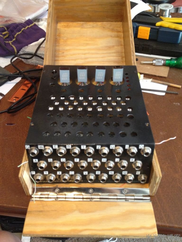
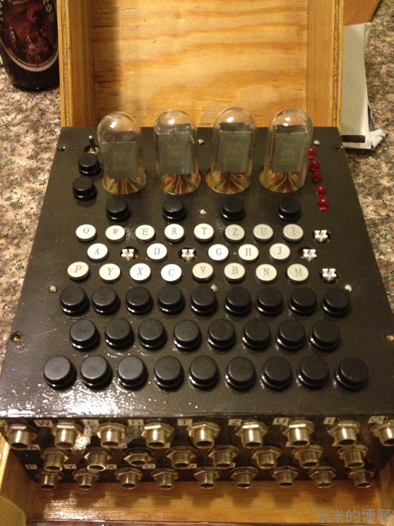
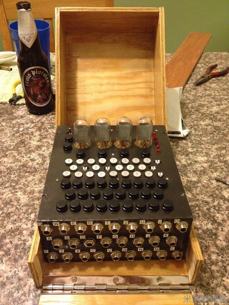
Step 5: Make a Box and Cut & Drill the Top Plate.
第五步:门面工夫 —— 做个盒子钻出面板
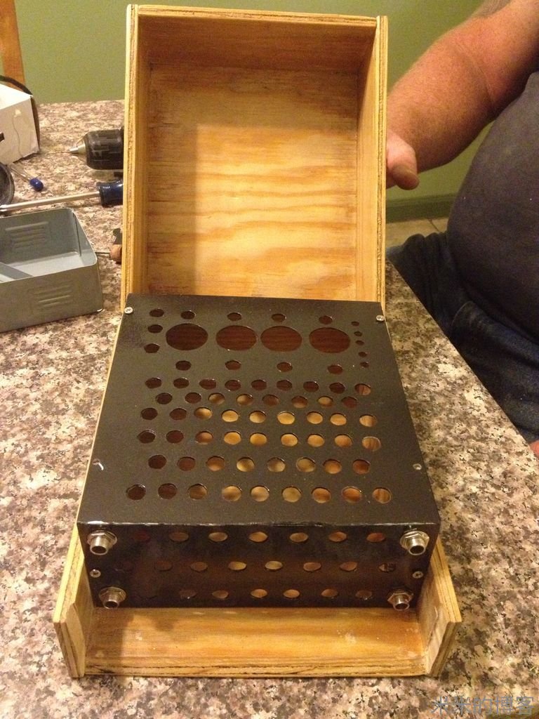
After obtaining the exact dimensions of the original M4 wooden box, we purchased a sheet of plywood & cut it in pieces so we could assemble our case.
在原版 M4 型木盒内得到确定位置数据后,我们买了一块胶合板,将它切块,然后砌盒子。
We decided to cut a steel plate from an obsolete rack mounted server as it had just the right thickness of metal for our needs. After making a transparency that showed where every button/lamp was located & cutting it out, we were able to superimpose it on the metal piece and draw each required hole with a sharpie.
我们从旧服务器机架上卸了一块钢板,厚度正合需要。将模具(上面早已画好每个按键和灯位,并切好了洞洞)盖在钢板上,然后用记号笔画出需要切出的洞洞。
We then spray painted it textured black to look like the real Enigma.
接着,我们用喷漆把它涂黑,就像真的 Enigma 机那样。
Step 6: Integration Tests
第六步:组装测试
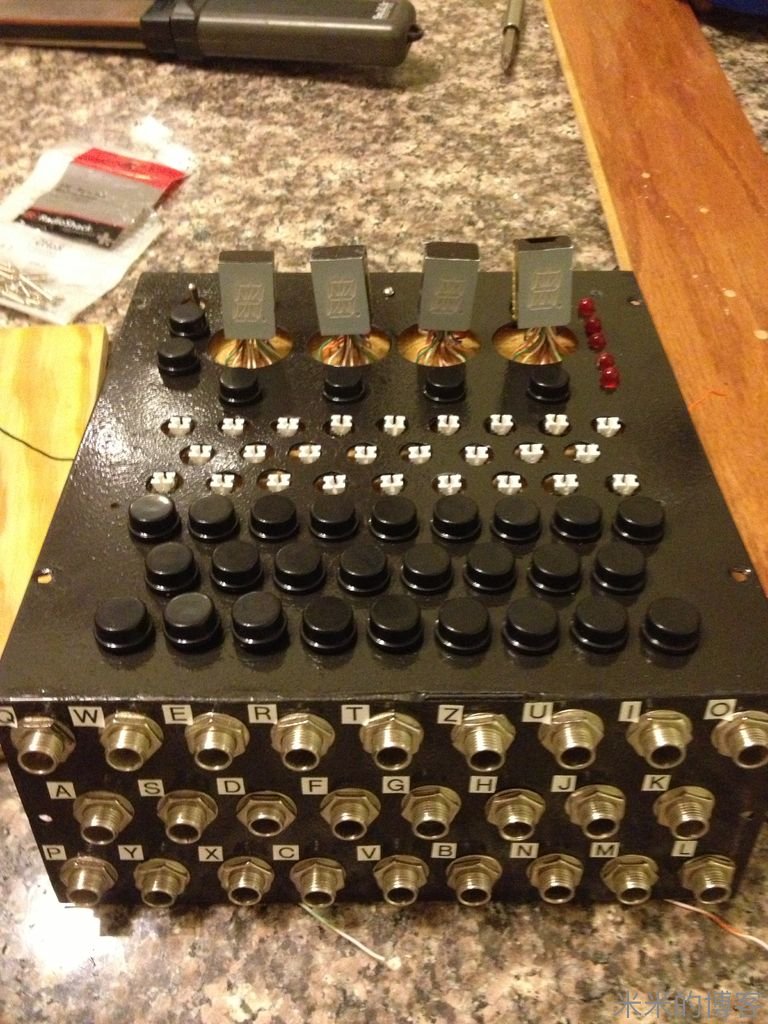
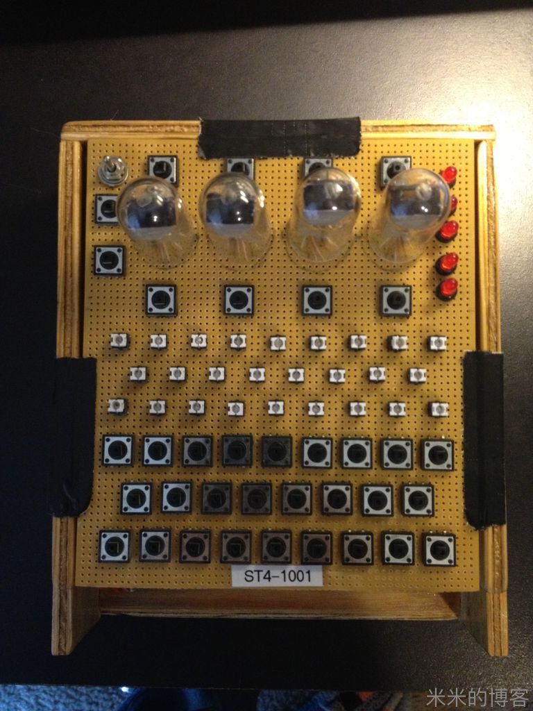
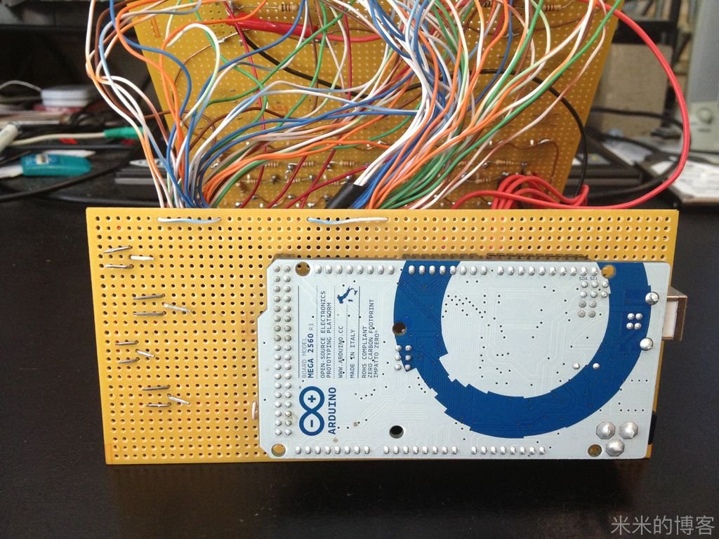
First is the permanent fitting of the metal plate on top of the perfboard making sure every button is working and every LED can shine.
首先把金属板在面包版上永久固定,确保所有按键正常工作,所有 LED 都能发光。
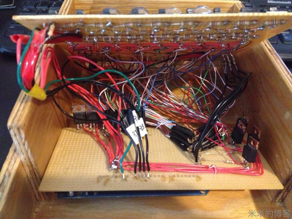
Then is the fitting of this solid assembly into the wooden case ensuring we didn't introduce a short anywhere.
接着就是把这一大坨东东装入木盒,确保没有空隙位置。
Step 7: Software - Ohhhh.... Ouch!
第七步:软件啊,日完软啊!
During each hardware assembly phase, we had created small Arduino sketches that would test the specific individual section we were working on:
在组装硬件过程中,我们也写了个小型 Arduino 程序框架,用以测试特定几个需要关注的部分:
A code that tests that each keyboard button is read accurately.
A second code that tests each of the 10 function buttons.
用来测试每个按键信号能准确读取,还有测试 10 个功能按键的代码。
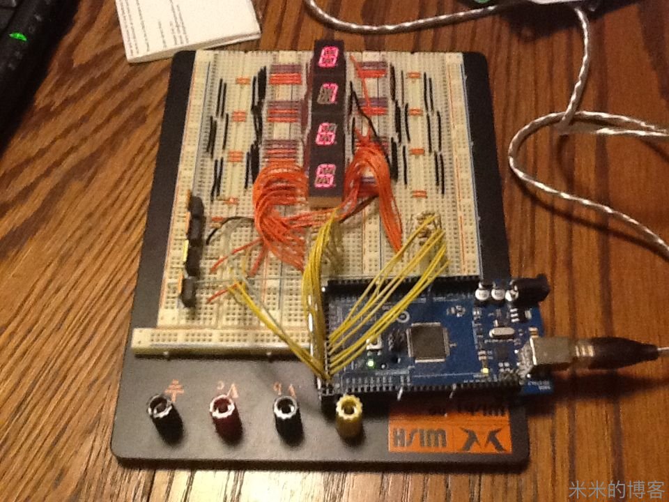
An Enigma_POST (Power On Self Test) sketch that tests that each keyboard lamp can be lit precisely and move each LED through each mode, with some modifications to the original breadboard code to ensure each segment of the 4 16-Segment LEDs is working perfectly.
Enigma_POST(上电自检)确保在每种模式下所有键盘等都能准确亮起,在每种模式下每个 LED 信号都能传送。我们对原本面包板上的代码做了修正,确保 4 个 16 段 LED 显示的每个部件无懈可击。
But, even with all these sample codes on hand that tested every piece of hardware on the machine, the task of reproducing the encrypting/decrypting functionality of a real M4 Enigma was a Mathematics tour-de-force!
但,即使所有手上的程序片段都说明机器状态完好,重现 M4 海军型 Enigma 机加解密功能,数学方面居功至伟。
All Arduino sketches will be available on our Github that we are currently setting up.
所有的 Arduino 程序片段即将在我们刚刚建好的Github 组织中发布。
Here is the Enigma_POST sketch:
以下是 Enigma_POST 程序片段(上电自检):1
2
3
4
5
6
7
8
9
10
11
12
13
14
15
16
17
18
19
20
21
22
23
24
25
26
27
28
29
30
31
32
33
34
35
36
37
38
39
40
41
42
43
44
45
46
47
48
49
50
51
52
53
54
55
56
57
58
59
60
61
62
63
64
65
66
67
68
69
70
71
72
73
74
75
76
77
78
79
80
81
82
83
84
85
86
87
88
89
90
91
92
93
94
95
96
97
98
99
100
101
102
103
104
105
106
107
108
109
110
111
112
113
114
115
116
117
118
119
120
121
122
123
124
125
126
127
128
129
130
131
132
133
134
135
136
137
138
139
140
141
142
143
144
145
146
147
148
149
150
151/* Enigma Development Code to Test each of the 4 Nixies, the 5 LEDs,
then Turn On each Lamp in sequence.
Written by Marc Tessier & James Sanderson 9/8/13
*/
// Define the 16-Segments Pins
int segment[17] = { 24,22,25,31,38,36,32,30,28,26,23,27,33,35,34,29,37 };
int anode[4] = { 39,41,43,45 };
// Define the 9 lamps Pins
int lamp[9] = { 10,9,8,7,6,5,4,3,2 };
int lanode[3] = { 11,12,13 };
// LTP587P Segments: A,B,C,D,E,F,G,H,K,M,N,P,R,S,T,U,dp
boolean segmentvals[39][17] = {
{ 0,0,0,0,1,1,0,0,1,1,1,0,1,1,1,0,1 }, // = A
{ 0,0,0,0,0,0,1,1,1,0,1,0,1,0,1,1,1 }, // = B
{ 0,0,1,1,0,0,0,0,1,1,1,1,1,1,1,1,1 }, // = C
{ 0,0,0,0,0,0,1,1,1,0,1,1,1,0,1,1,1 }, // = D
{ 0,0,1,1,0,0,0,0,1,1,1,0,1,1,1,0,1 }, // = E
{ 0,0,1,1,1,1,0,0,1,1,1,0,1,1,1,0,1 }, // = F
{ 0,0,1,0,0,0,0,0,1,1,1,0,1,1,1,1,1 }, // = G
{ 1,1,0,0,1,1,0,0,1,1,1,0,1,1,1,0,1 }, // = H
{ 0,0,1,1,0,0,1,1,1,0,1,1,1,0,1,1,1 }, // = I
{ 1,1,0,0,0,0,0,1,1,1,1,1,1,1,1,1,1 }, // = J
{ 1,1,1,1,1,1,0,0,1,1,0,1,0,1,1,0,1 }, // = K
{ 1,1,1,1,0,0,0,0,1,1,1,1,1,1,1,1,1 }, // = L
{ 1,1,0,0,1,1,0,0,0,1,0,1,1,1,1,1,1 }, // = M
{ 1,1,0,0,1,1,0,0,0,1,1,1,0,1,1,1,1 }, // = N
{ 0,0,0,0,0,0,0,0,1,1,1,1,1,1,1,1,1 }, // = O
{ 0,0,0,1,1,1,0,0,1,1,1,0,1,1,1,0,1 }, // = P
{ 0,0,0,0,0,0,0,0,1,1,1,1,0,1,1,1,1 }, // = Q
{ 0,0,0,1,1,1,0,0,1,1,1,0,0,1,1,0,1 }, // = R
{ 0,0,1,0,0,0,1,0,1,1,1,0,1,1,1,0,1 }, // = S
{ 0,0,1,1,1,1,1,1,1,0,1,1,1,0,1,1,1 }, // = T
{ 1,1,0,0,0,0,0,0,1,1,1,1,1,1,1,1,1 }, // = U
{ 1,1,1,1,1,1,0,0,1,1,0,1,1,1,0,1,1 }, // = V
{ 1,1,0,0,1,1,0,0,1,1,1,1,0,1,0,1,1 }, // = W
{ 1,1,1,1,1,1,1,1,0,1,0,1,0,1,0,1,1 }, // = X
{ 1,1,1,1,1,1,1,1,0,1,0,1,1,0,1,1,1 }, // = Y
{ 0,0,1,1,0,0,1,1,1,1,0,1,1,1,0,1,1 }, // = Z
{ 0,0,0,0,0,0,0,0,1,1,0,1,1,1,0,1,1 }, // = 0
{ 1,1,0,0,1,1,1,1,1,1,0,1,1,1,1,1,1 }, // = 1
{ 0,0,0,1,0,0,0,1,1,1,1,0,1,1,1,0,1 }, // = 2
{ 0,0,0,0,0,0,1,1,1,1,1,0,1,1,1,1,1 }, // = 3
{ 1,1,0,0,1,1,1,0,1,1,1,0,1,1,1,0,1 }, // = 4
{ 0,0,1,0,0,0,1,0,1,1,1,0,1,1,1,0,1 }, // = 5
{ 0,0,1,0,0,0,0,0,1,1,1,0,1,1,1,0,1 }, // = 6
{ 0,0,0,0,1,1,1,1,1,1,1,1,1,1,1,1,1 }, // = 7
{ 0,0,0,0,0,0,0,0,1,1,1,0,1,1,1,0,1 }, // = 8
{ 0,0,0,0,0,0,1,0,1,1,1,0,1,1,1,0,1 }, // = 9
{ 1,1,1,1,1,1,1,1,1,1,1,1,1,1,1,1,1 }, // = Space
{ 0,0,0,0,0,0,0,0,0,0,0,0,0,0,0,0,0 }, // = Full Lit
{ 1,0,1,0,1,0,1,0,1,0,1,0,1,0,1,0,1 } // = SS
};
// LTP587P Segments: A,B,C,D,E,F,G,H,K,M,N,P,R,S,T,U,dp
boolean lampvals[9][9] = {
{ 0,1,1,1,1,1,1,1,1 }, // = Q or A or P
{ 1,0,1,1,1,1,1,1,1 }, // = W or S or Y
{ 1,1,0,1,1,1,1,1,1 }, // = E or D or X
{ 1,1,1,0,1,1,1,1,1 }, // = R or F or C
{ 1,1,1,1,0,1,1,1,1 }, // = T or G or V
{ 1,1,1,1,1,0,1,1,1 }, // = Z or H or B
{ 1,1,1,1,1,1,0,1,1 }, // = U or J or N
{ 1,1,1,1,1,1,1,0,1 }, // = I or K or M
{ 1,1,1,1,1,1,1,1,0 } // = O or L
};
int value_row1 = 0;
int value_row2 = 0;
int value_row3 = 0;
char key = 91;
int led1 = 40;
int led2 = 42;
int led3 = 44;
int led4 = 46;
int led5 = 48;
int wait = 100;
void setup() {
for (int index = 0; index <= 3; index++) {
pinMode(anode[index], OUTPUT);
digitalWrite(anode[index], 1);
}
for (int index = 0; index <= 16; index++) {
pinMode(segment[index], OUTPUT);
digitalWrite(segment[index], 1);
}
// initialize the digital pins as an output.
pinMode(led1, OUTPUT);
pinMode(led2, OUTPUT);
pinMode(led3, OUTPUT);
pinMode(led4, OUTPUT);
pinMode(led5, OUTPUT);
for (int index = 0; index <= 2; index++) {
pinMode (lanode[index], OUTPUT);
digitalWrite (lanode[index], 1);
}
for (int index = 0; index <= 8; index++) {
pinMode(lamp[index], OUTPUT);
digitalWrite(lamp[index], 1);
}
}
void loop() {
sixteenSegWrite(0, 38);
sixteenSegWrite(1, 38);
sixteenSegWrite(2, 38);
sixteenSegWrite(3, 38);
digitalWrite(led1, HIGH); // turn the LED on (HIGH is the voltage level)
delay(200); // wait for a second
digitalWrite(led1, LOW); // turn the LED off by making the voltage LOW
delay(wait); // wait for a second
digitalWrite(led2, HIGH); // turn the LED on (HIGH is the voltage level)
delay(200); // wait for a second
digitalWrite(led2, LOW); // turn the LED off by making the voltage LOW
delay(wait); // wait for a second
digitalWrite(led3, HIGH); // turn the LED on (HIGH is the voltage level)
delay(200); // wait for a second
digitalWrite(led3, LOW); // turn the LED off by making the voltage LOW
delay(wait); // wait for a second
digitalWrite(led4, HIGH); // turn the LED on (HIGH is the voltage level)
delay(200); // wait for a second
digitalWrite(led4, LOW); // turn the LED off by making the voltage LOW
delay(wait); // wait for a second
digitalWrite(led5, HIGH); // turn the LED on (HIGH is the voltage level)
delay(200); // wait for a second
digitalWrite(led5, LOW); // turn the LED off by making the voltage LOW
delay(wait); // wait for a second
for (int index = 0; index <= 2; index++) {
digitalWrite(lanode[index], 0);
for (int mychar = 0; mychar < 9; mychar++) {
for (int sindex = 0; sindex < 9; sindex++) {
digitalWrite(lamp[sindex], lampvals[mychar][sindex]);
delay(30);
}
}
digitalWrite(lanode[index], 1);
}
}
void sixteenSegWrite(int digit, int character) {
digitalWrite(anode[digit],0);
for (int index = 0; index < 17; index++) {
digitalWrite(segment[index], segmentvals[character][index]);
}
}
Step 8: More Software!
第八步:再多一些软件!
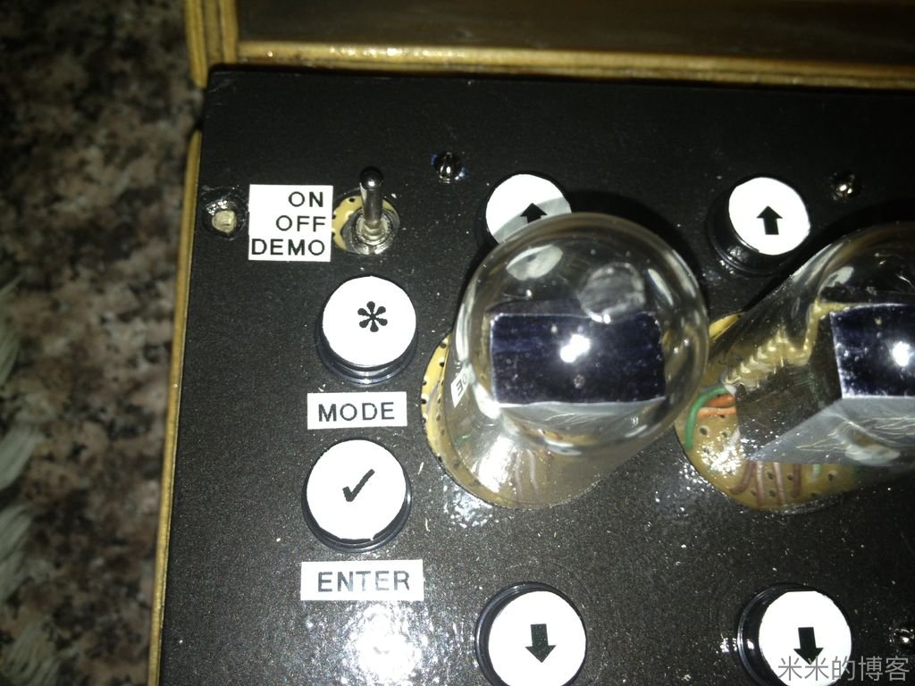
So we first created a function for each mode the Enigma operates in:
首先,我们写了个函数,给每个 Enigma 机工作模式用。
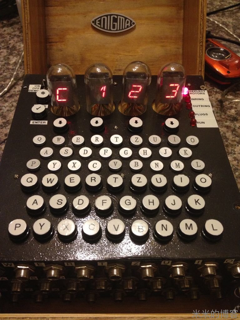
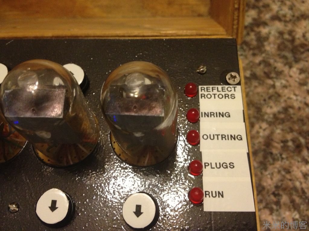
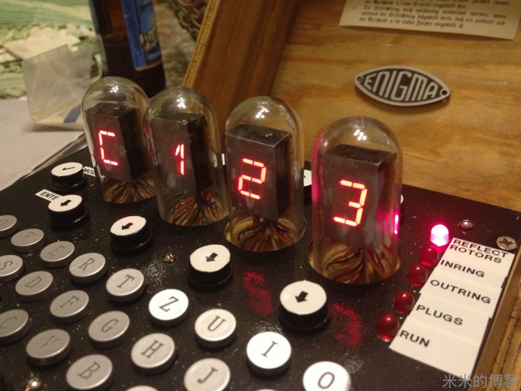
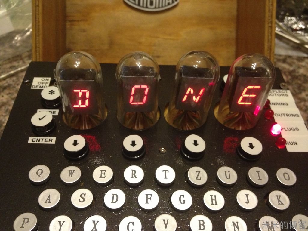
In Mode 0, Default Mode, the Enigma is nothing but a simple typewriter with a Marquee that displays its Model Number.
在模式 0、默认模式,Enigma 机仅仅是一台普通打字机,以跑马灯方式显示它的型号。
Mode 1 allows the user to select the 3 (out of 8) Rotors he will use along with which one (of the 2) Reflector he wants to use.
模式 1 下,允许用户从八个转子中选取三个,两个反射器中选择一个进行使用。
In Mode 2, the user can select the Internal position of each Rotor.
模式 2 下,允许用户排列转子次序。
Mode 3 is used to specify the starting (external) position of each Rotor.
模式 3 用于自定义转子初始字母排列。
In Mode 4, a user can enter up to 10 Swapped pairs of letters.
选择模式 4,用户最多可以使用接线板上 10 对交换字母排列。
Mode 5 is Run mode and at that point, the Enigma will encrypt or decrypt any letter typed on the keyboard.
模式 5 是运行模式,此时 Enigma 机能加解密任何从键盘录入的信息。
Here is the Complete sketch that runs the whole Enigma:
以下是整个 Enigma 机工作流程完整程序片段:
Open Enigma M4 Plugboard.ino
IF there is enough interest, we plan on are creating a PCB that would will allow for a much easier assembly of this wonderful fully functional Enigma replica. Please visit http://www.stgeotronics.com to find out about availability, pricing & to place your order or pre-order now. The Circuit schematics are published, so the PCB has entered it's development stage. Soon to be tested.
如果有足够的利润,我们将研发能够使全功能 Enigma 机复制品装载更为容易的印刷电路板。请登陆 http://www.stgeotronics.com 查询商品上架与否、价格、下单或预订吧。电路图已经发布了,印刷电路也已进入开发阶段,即将内测。
Step 9: Circuit Schematics
第九步:电路图
In response to the popular demand, here are the two Circuit Schematics.
徇众要求,电路图两份在此。
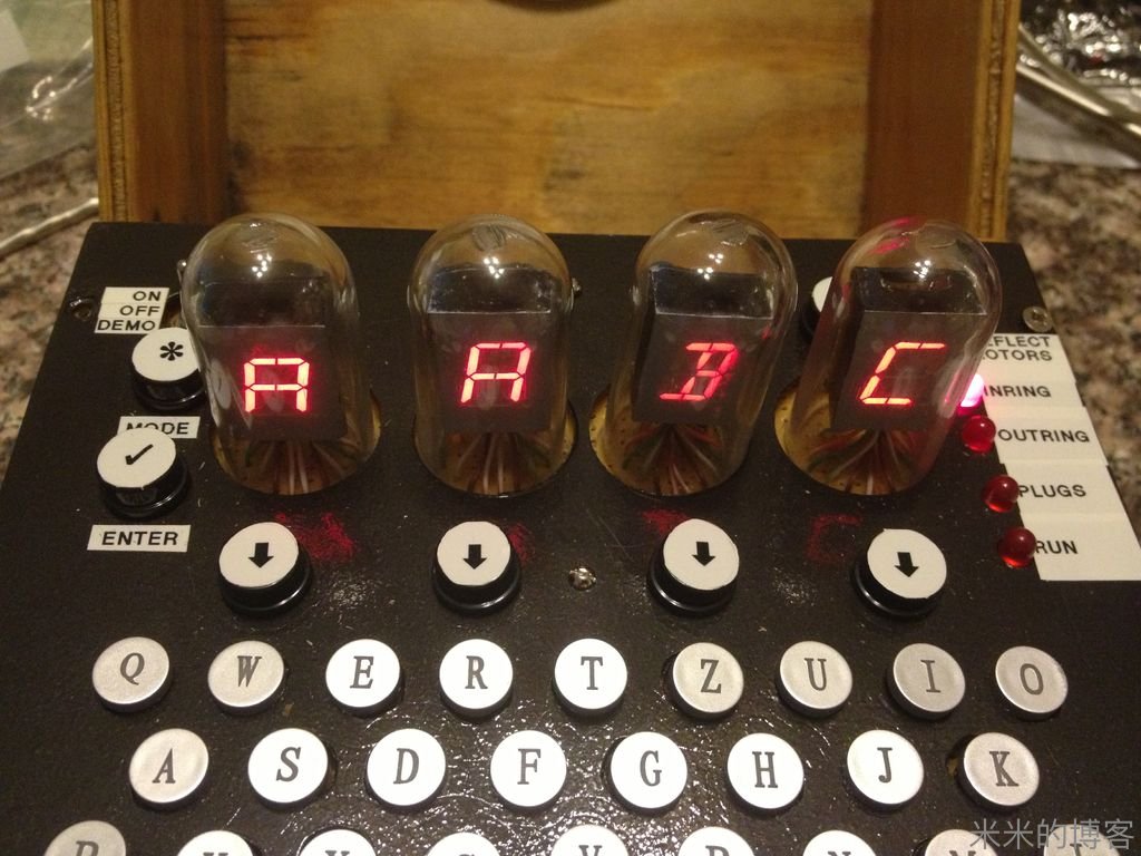
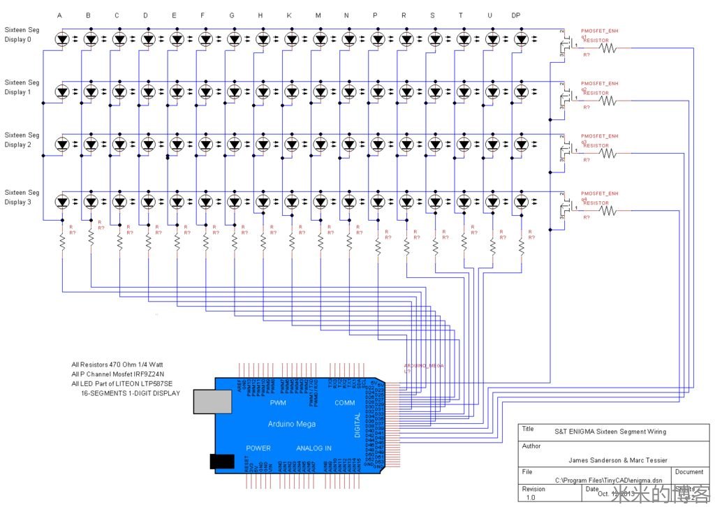
The first one shows how our fake nixie tubes (the 4 elevated 16-Segment units) are wired in order to provide the response that the rotors provide on a real Enigma machine. They are also used in each setup mode to provide feedback on the setting up of the machine.
第一个是仿电子管(4 个 16 段显示单元)如何布线,用于显示转子在 Enigma 机上的输出信号。同时,它们也用于每种调试模式,反馈用户机器设定信息。
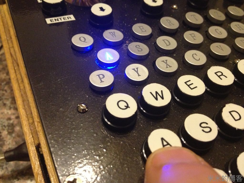
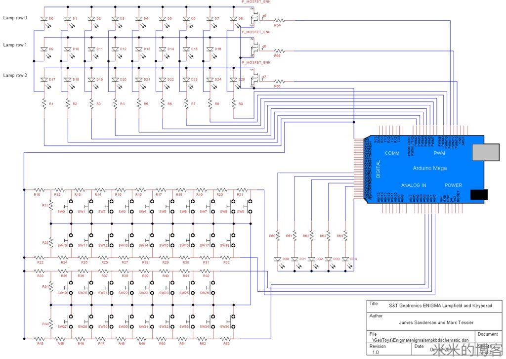
The second one shows how each of the 26 keyboard buttons and 10 function keys, the 26 key lamps & the 5 LEDs are all wired.
第二幅电路图显示 26 个字母按键及 10 个功能键、26 个键盘灯和 5 个 LED 是如何布线的。
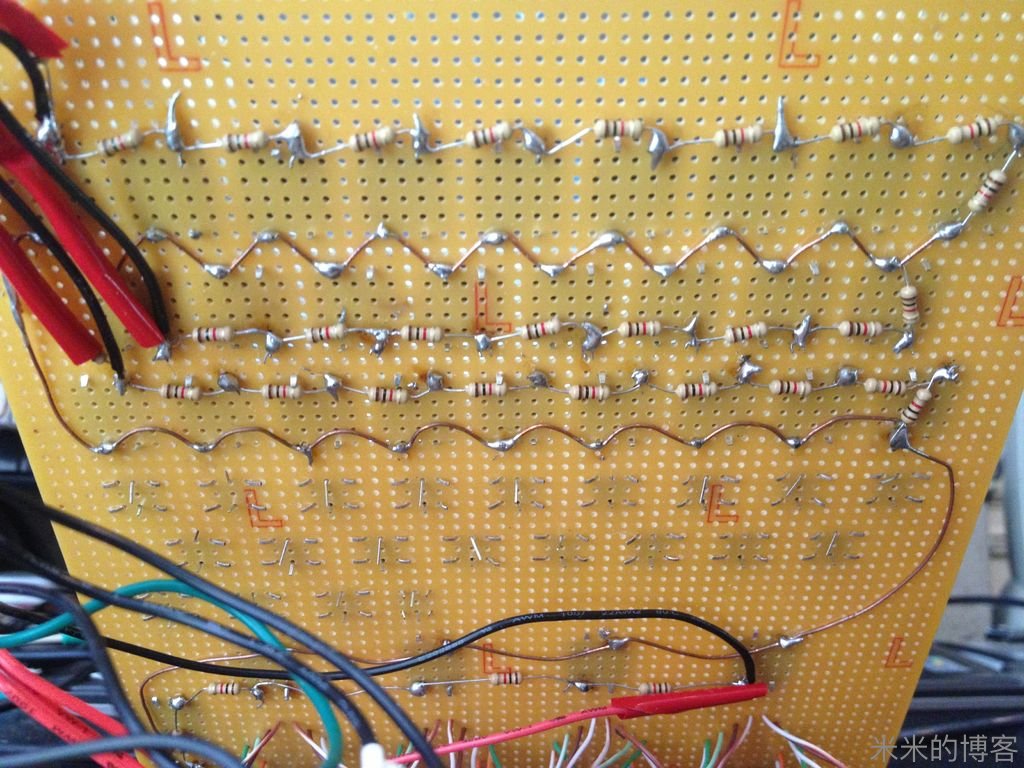
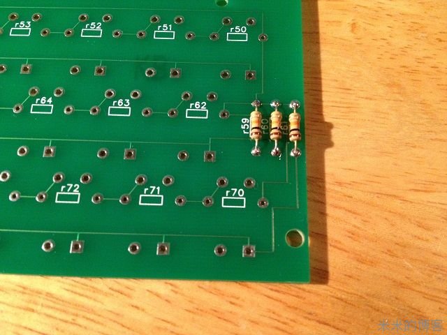
All LED resistors are 470 Ohms and all Pushbutton resistors are 1KOhm.
所有 LED 电阻都是 470 欧,而开关电阻则都是 1 千欧。
Stay tuned for the PCB design file...
印刷电路设计档仍在修正中。
We hope you enjoyed our first Instructable!
希望你享受我们第一份制作教程!
Thank You for your time.
感谢你抽出宝贵时间阅读!
Step 10: Prototype Boards
第十步:PCB 样机版
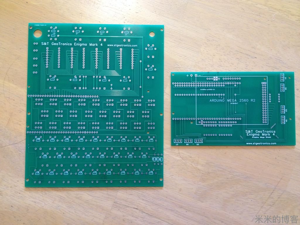
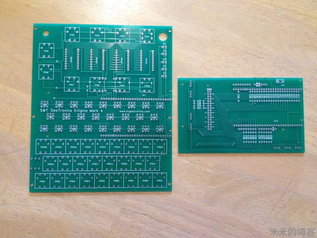
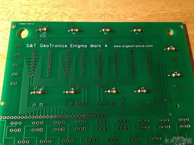
Due to popular demand, we designed & ordered some Printed Circuit Boards. Well, our PCBs are finally in and at first glance, they look beautiful! We have been busy populating & testing one to make sure it performs as good as it looks and more importantly, as well as our proof-of-concept device.
徇众要求,我们设计及定制了一些印刷电路板。它们终于面世了,如此清纯可爱!我们忙于组装,并测试其中一块样品,确保它在功能上与外观一样完美无暇。更重要的是,能实现和那台原型测试机一样的功能。
The boards we ordered are almost perfect: they each need a little jumper wire to fix a small design flaw. This small flaw does not affect behavior or functionality and is an easy fix.
订购回来的底板几乎完美,只需一点引脚线去修补设计瑕疵。而这些瑕疵对功能没有影响,修理它们是小菜一碟。
With this jumper in place, you can now make your own Enigma Replica much easier & faster than running all wires this instructable shows. So, we are now happy to report that testing is completed & the new boards work just fine!
有了这些引脚,你能更容易制作自己的 Enigma 复刻机,比起教程里的布线方便多了。我们在此很高兴宣布,测试完成,新型板一样给力!
We are now accepting orders at www.stgeotronics.com & have started shipping.
Pictures of the assembly have been added as Step 11.
下单订购请登陆 http://www.stgeotronics.com ,已发货热卖中。组装图片请见第十一步。
Thank You for your overwhelming support & wonderful feedback!
感谢大家的不懈支持和宝贵反馈意见!
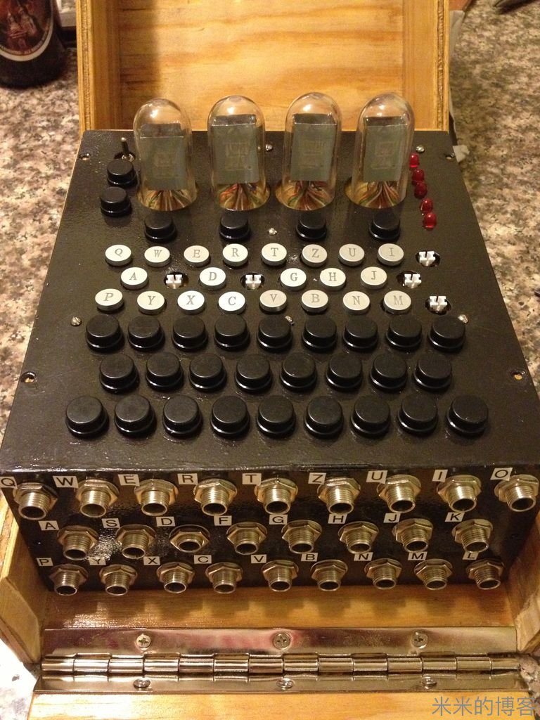
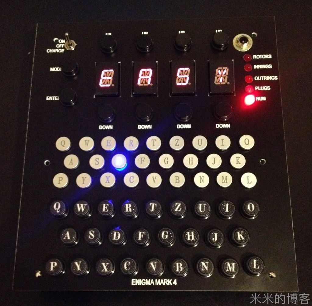
Step 11: Assembled Kits
第十一步:组装完成的作品
更多图片可以前往原文查看。
This assembly took one evening & you can look at assembly pictures above for an overview of the process.
花了一晚上组装完成,全过程的概览如上图所示。
Thank You for the support & feedback!
感谢你的支持与反馈!
更多
笔者在深入了解 Enigma 机后,制作了一个 JavaScript 版本的虚拟机,实现了几乎全部功能,可以点击下方链接前往。
本站的 JavaScript 版本:ZSQ.IM > 应用 > 原创游戏 > Enigma
这个版本通过flex布局,在不同大小的屏幕上都可以正常显示,不过还是建议使用桌面端打开。
而原文中基于 Arduino 开发的实体机器,由于制作过于复杂,笔者还在进行研究。原作者提供了所有的代码,因此完全可以按照同样的思路来实现。